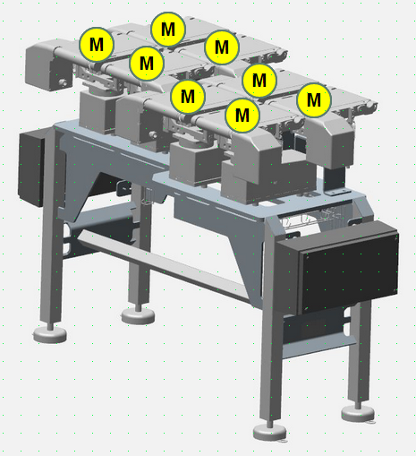
This weigh machine includes eight conveyors, where four of them are assembled on a separate weigher unit creating four weigh-paths. The other four acceleration motors speed up the product, to reach a longer distance between each of them.
How it works?
A product is accelerated on the acceleration conveyor before it is weighed on the next module. The purpose for this behaviour is the get the longer distance between products, where only one product is being weighed, not two or more nor parts of the next product. The weigh-time depends from the speed of the conveyor and can be adjusted. The longer time, the lower transmition speed of the product. Here the conveyor is set to 60ms for one weigh-cycle.
A photoelectric sensor was mounted on the weigher modul, which signals to the PLC controller that a new weigh-value is ready for reading.
As the timing is very critical and has been set to milliseconds, we cannot use OPCUA-server obviously, as this technology is not predictive and can have delays between 10ms til over 100ms. Instead a GPIO must be used here.


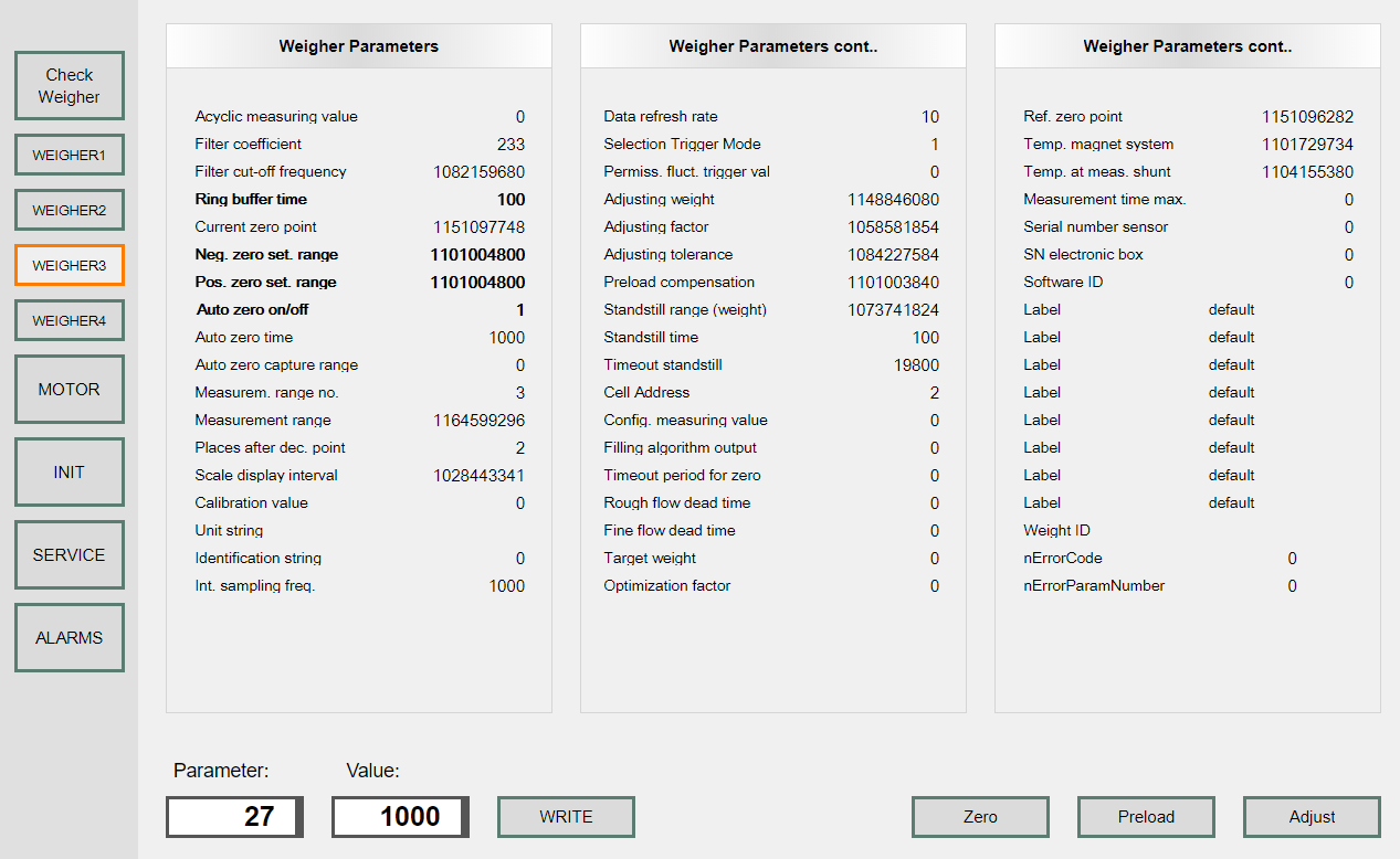
The parameters of the checkweigher
To controll the checkweigher one have to set some parameters. The important values has been depicted bolded and have direct influance for the weighing machine. To read and write parameters a dedicated routine has been programmed, which use the acyclic state communication between the weigher and the CFI (controller module).
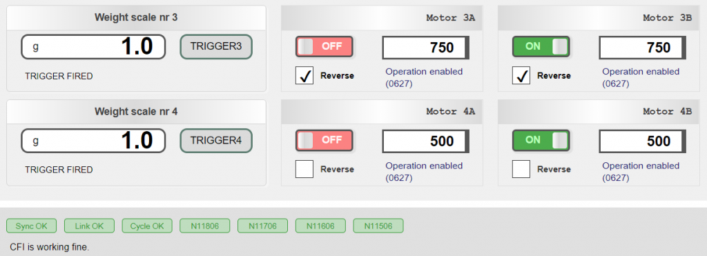
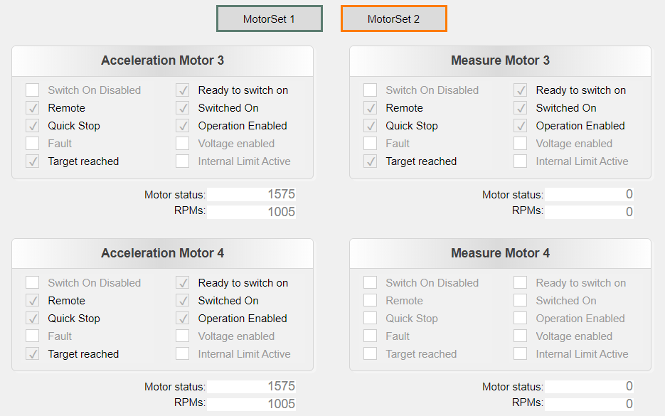
The motors
To show the state of the motors two sets was created with four motors each. In fact 4 sets would be better, as one set includes two motors: the acceleration and the measure motor. The control of the motor is similar to the weigher module and the states of the motors are showed below:
Here follows an example of the control code:
void CheckWeightMotor::Cyclic()
{
	unsigned short nLocalStatusWord;

	// get the current motor-state
	nLocalStatusWord = motorIO->stIn.stSub1.nStatusWord;
	this->displayStatus(nLocalStatusWord);

	// Transition 7, 9, 10, 12
	if (!controls->myVoltageSwitch) {
		motorIO->stOut.stSub1.nControlWord &= ~(1 << 1);	// bit 1: disable voltage
		return;
	}

	// xxxx xxxx x0xx 0000 (state: Not ready to switch on)
	if ((nLocalStatusWord & 0x004F) == 0x0000)
	{
		// bit 1: enable voltage
		motorIO->stOut.stSub1.nControlWord |= (1 << 1);
	}

	// 0x0240: 0000 0010 0100 0000: Switch on disabled (bit 6) and Remote (bit 9)
	// Remote bit don't counts
	// xxxx xxxx x1xx 0000 (state: Switch on disabled)
	else if ((nLocalStatusWord & 0x004F) == 0x0040)
	{
		// Transition 2: SWITCH ON DISABLED ? READY TO SWITCH ON
		// Bit 1 Disable Voltage and Bit 2 Quick Stop are set in the Control word (Shut-down command).
		// DClink voltage may be present.
		motorIO->stOut.stSub1.nControlWord &= ~(1 << 0);	// bit 0: switch on
		motorIO->stOut.stSub1.nControlWord |= (1 << 1);		// bit 1: enable voltage
		motorIO->stOut.stSub1.nControlWord |= (1 << 2);		// bit 2: set quick stop

	}
	// xxxx xxxx x01x 0001 (state Ready to switch on)
	else if ((nLocalStatusWord & 0x006F) == 0x0021)
	{
		// Transition 3: READY TO SWITCH ON ? SWITCHED ON
		// High voltage may be applied to the drive.
		motorIO->stOut.stSub1.nControlWord |= (1 << 0);		// bit 0: switch on
		motorIO->stOut.stSub1.nControlWord |= (1 << 1);		// bit 1: enable voltage
		motorIO->stOut.stSub1.nControlWord |= (1 << 2);		// bit 2: quick stop
		motorIO->stOut.stSub1.nControlWord &= ~(1 << 3);	// bit 3: enable operation
	}
	// xxxx xxxx x01x 0011 (state Switched on)
	else if ((nLocalStatusWord & 0x006F) == 0x0023)
	{
		// Transition 4: SWITCHED ON ? OPERATION ENABLE
		//	ss << "Switched on";
		motorIO->stOut.stSub1.nControlWord |= (1 << 0);	// bit 0: switch on
		motorIO->stOut.stSub1.nControlWord |= (1 << 1);	// bit 1: enable voltage
		motorIO->stOut.stSub1.nControlWord |= (1 << 2);	// bit 2: set quick stop
		motorIO->stOut.stSub1.nControlWord |= (1 << 3);	// bit 3: enable operation
	}
	// xxxx xxxx x01x 0111 (state: Operation enabled)
	else if ((nLocalStatusWord & 0x006F) == 0x0027)
	{
		// set the desired speed (mm/sec)
		// radius of antriebswelle (driveshaft) = 0.038/2 [m]
		// transmission = 4
		// nLinearSpeed = 0.75 [m/s]
		// rpm = (60*transmission*nLinearSpeed)/(2*PI*drive_radius)
		controls->nLinearSpeed = nLinearSpeed;
		if (controls->nLinearSpeed <= 1000) {
			controls->myRPM = (unsigned short) (((60 * transmission * controls->nLinearSpeed) / 1000)
				/ (2 * pi * (driveshaft / 2)));
			if (controls->myReverse) {
				motorIO->stOut.stSub1.nSetSpeed = -1 * controls->myRPM;
			}
			else {
				motorIO->stOut.stSub1.nSetSpeed = 1 * controls->myRPM;
			}
		}
	}
	// xxxx xxxx x00x 0111 (Quick stop active)
	else if ((nLocalStatusWord & 0x006F) == 0x0007)
	{
		motorIO->stOut.stSub1.nControlWord &= ~(1 << 1);	// bit 1: enable voltage
	}
	// xxxx xxxx x0xx 1111 (Fault reaction active)
	else if ((nLocalStatusWord & 0x004F) == 0x000F)
	{
		//Transition 14: FAULT REACTION ACTIVE ? FAULT
	}
	// xxxx xxxx x0xx 1000 (Fault)
	else if ((nLocalStatusWord & 0x004F) == 0x0008)
	{
		//Transition 15: FAULT ? SWITCH ON DISABLED
		// must create a button 'Reset'
		//if (myResetButton) {
		// stImot1a.stOut.stSub1.nControlWord |= (1 << 7);	// bit 7: fault reset
		// myResetButton = 0;
		//}
	}

	else {
		//	ss << "Some other state: ";
	}
}