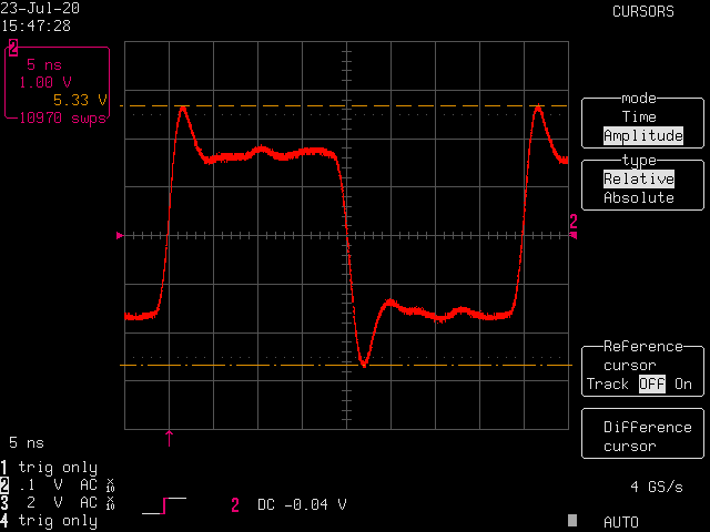
Transmitting line of the PHY chip was observed on this belowed diagram. The used PHY chip was 83822 from Texas Instruments and the used microcontroller was the XMC4800-2048 from Infineon. The red/green are transmitting signals, the blue is the 25MHz clock from the µC, and the lilla is the transmitting clock from the µC.
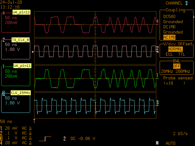

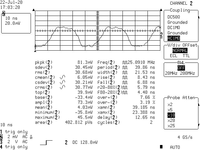
The 25MHz-clock examination
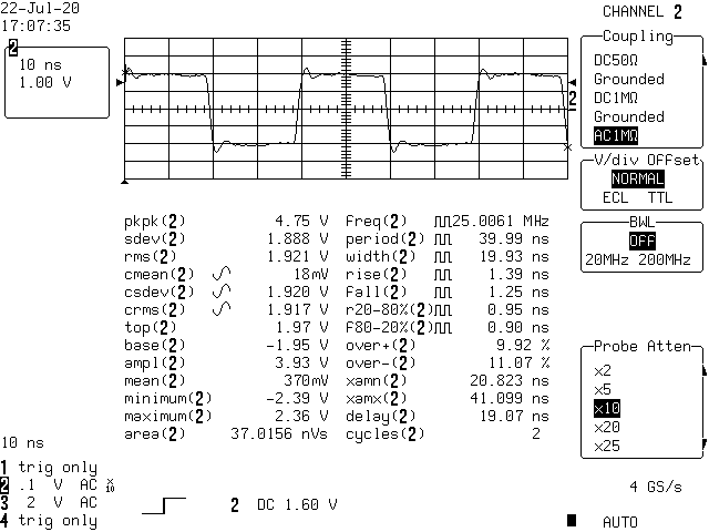
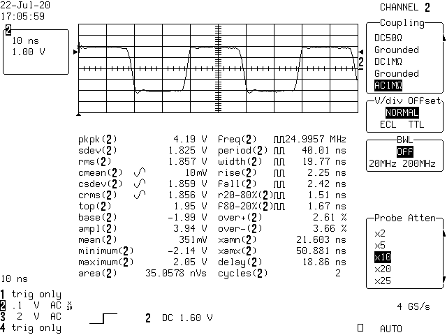
As the clocking of the PHY chip is the very important to achieve its stable work, so the best method is to check the signal quality with an oscilloscope.
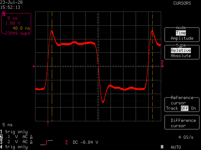
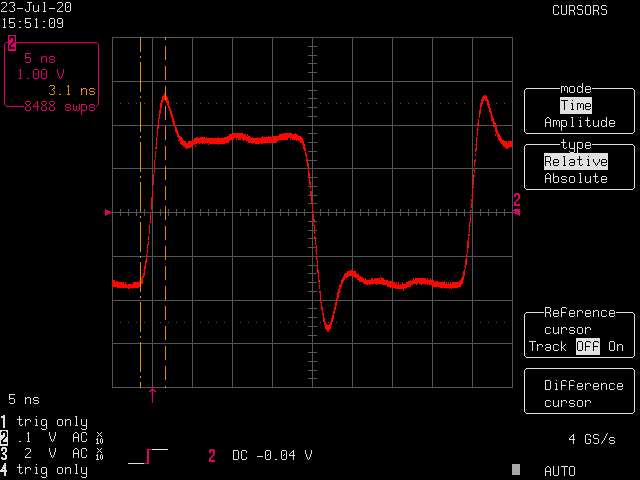
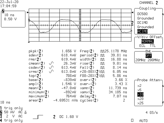
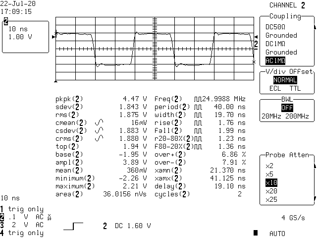
The ringing on the clockline observed on these diagrams must be significantly reduced. The very common methode is to insert a 49 Ohm inseries with the clock line just behind the 25MHz-clock-leg of the microcontroller. Adding a driver cause the opposite: the signal rings even more.
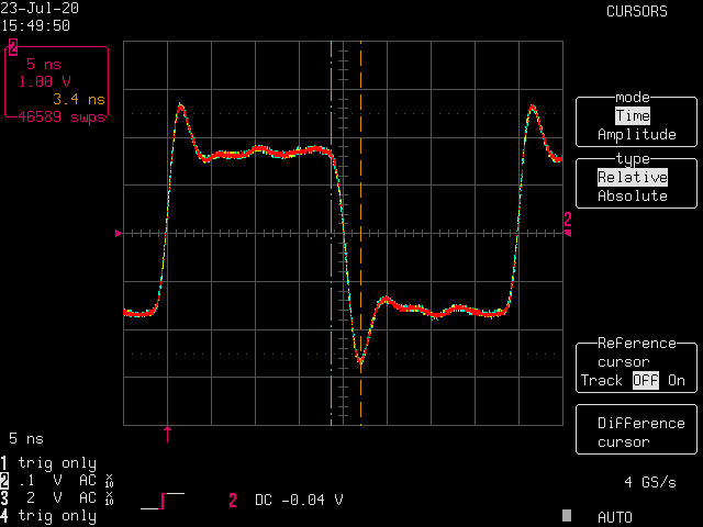
Edge and strength adjustment of the clock signal
For some reason one can manipulate the strength of the signal produced inside of the µC. There three differend strengths one can adjust with different edges:
- STRENGTH_STRONG_SLOW_EDGE
- STRENGTH_STRONG_SHARP_EDGE
- STRENGTH_STRONG_MEDIUM_EDGE
- STRENGTH_MEDIUM
- STRENGTH_WEAK
- STRENGTH_WEAK
- STRENGTH_MEDIUM
- STRENGTH_STRONG_SLOW_EDGE
- STRENGTH_STRONG_SHARP_EDGE
- STRENGTH_STRONG_MEDIUM_EDGE
One response to “PHY TX line”
just a comment